AC and solar charging can run together on a portable power station when the manufacturer explicitly supports that combination for your exact model. Check the source priority and combined limits before connecting both, then budget the energy left after any devices running during the stop. Two input sockets and two separate maximum ratings don’t establish simultaneous support.
For example, Anker’s US FAQs for the SOLIX C1000 Gen 2 and SOLIX C2000 Gen 2 say that grid and solar charging can operate simultaneously, with solar prioritized and AC supplying the remaining capacity. That statement applies to those models. It doesn’t give permission to combine sources on another station or prove that the two advertised peak input ratings add together.
The five checks below help you turn that support statement into a useful charging plan. They cover a portable station’s documented inputs; they don’t provide wiring or fixed electrical installation instructions.
1. Confirm AC and solar charging support for the exact model
Start with the model number, generation and regional version printed on the station. Find its manual and current manufacturer support page. A familiar product name can cover several generations with different charging hardware or operating modes.
Look for a statement naming both mains or grid input and solar input at the same time. If the manual lists those charging methods separately, ask support whether they may operate together. Save the answer with the exact model identification. An illustration showing both ports is useful for locating connections, but doesn’t answer the operating question.
Before planning AC and solar charging, distinguish these capabilities:
| Manufacturer wording | What you still need to establish |
|---|---|
| AC and solar charging simultaneously | Which modes, limits and source priority apply to both inputs |
| Charge while powering devices | Input/output operation, supported outlets and charging behavior under load |
| UPS or EPS function | Transfer behavior and supported loads when the incoming supply fails |
| Car or solar charging | Whether one shared port accepts either source; this alone doesn’t authorize both together |
| Two solar inputs | Per-input limits and permitted panel arrangements; it says nothing by itself about mains input |
AC and solar charging is a source-plus-source question. Running a fridge while recharging is a source-plus-load question. If you want to do both during the same stop, the manufacturer needs to support both arrangements and specify their applicable limits.
Keep the charging inputs and output outlets clearly identified. Use only the cables, adapters and connections permitted in the product documentation. Never connect the station’s AC output back to its own AC charging input, join independent sources with an improvised splitter, or assume a solar/car port supports both sources together.
For a broader view of panel selection and the related charging questions, start with the solar charging guides. This article begins after you’ve identified the exact station and its supported input arrangement.
2. Read AC and solar charging limits and source priority
A station can support AC and solar charging while still limiting the combined power. The individual AC maximum describes AC charging under its specified conditions; the solar maximum describes the solar input under its own conditions. A third combined limit, an active mode, or the battery’s present acceptance may govern operation with both connected.
The Anker Gen 2 FAQs cited above establish solar priority. They don’t establish an additive combined maximum in the passages used here. Don’t turn a support statement into a charging-speed promise by summing separate specification rows.
Consider a hypothetical station with these assumed conditions:
- A documented combined charging ceiling of 1,000W.
- Solar delivering 300W to its accepted input.
- AC capable of supplying 800W when used alone.
- A supported mode that prioritizes solar, with the battery currently able to accept the combined ceiling.
At that operating point, AC can supply the remaining 700W. The total is 1,000W. Adding 300W and 800W to promise 1,100W would exceed the assumed combined limit. These numbers illustrate the arithmetic; they are not C1000 Gen 2 or C2000 Gen 2 specifications.
If solar then falls to 100W, AC could supply up to its assumed 800W maximum, giving 900W total under those same conditions. The unused 100W of combined headroom doesn’t increase the separate AC limit. If a selected charging mode lowers the overall ceiling, repeat the calculation with that lower ceiling.
| Condition in this hypothetical example | Solar input | AC input | Total accepted input |
|---|---|---|---|
| Solar available; 1,000W combined ceiling | 300W | 700W | 1,000W |
| Solar falls; AC remains limited to 800W | 100W | 800W | 900W |
| A mode sets a 600W combined ceiling | 300W | 300W | 600W |
Actual control behavior needs the manufacturer’s documentation or a representative observation. A station might display separate source values, a combined input figure or a value with a different measurement boundary. Read the display explanation before comparing it with a wall meter.
Solar compatibility remains a separate requirement during AC and solar charging. Check the permitted voltage range, current, power, polarity and connector arrangement. A spare part of the combined power budget doesn’t make an otherwise incompatible solar array acceptable.
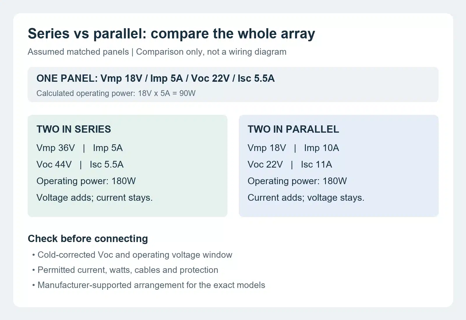
If several panels are involved, use the series-versus-parallel compatibility checks to assess their arrangement. If the station must stay away from the panels, use the solar extension cable checks to choose a permitted cable path. Neither decision can be replaced by the panel’s wattage label.
3. Budget the energy retained after AC and solar charging
The useful outcome of AC and solar charging is enough stored energy for the next session. A high input number on the screen doesn’t tell you how much energy reached the battery, especially when the station is also powering devices.
Power is a rate in watts. Energy over time is measured in watt-hours. For a steady assumed input, multiply watts by hours; for changing solar or charging power, use cumulative energy readings or intervals that reflect the changes. A single photograph of the input screen cannot establish the whole stop’s energy gain.
Here is a second hypothetical example. Assume a compatible, manufacturer-supported AC and solar charging session lasts one hour. The accepted inputs average 500W from AC and 100W from solar at the chosen input boundary. During that hour, supported outputs deliver 130Wh to connected devices. Also assume 50Wh is used in conversion and internal operation within that boundary.
| Energy accounting for the assumed one-hour stop | Energy |
|---|---|
| Accepted AC input: 500W × 1 hour | 500Wh |
| Accepted solar input: 100W × 1 hour | 100Wh |
| Total accepted input | 600Wh |
| Energy delivered through outputs | −130Wh |
| Assumed conversion and internal consumption | −50Wh |
| Estimated energy added to battery storage | 420Wh |
The 50Wh is an illustrative assumption, not a universal loss allowance or a measured result. A real station’s internal routing and reported values may use different boundaries. Account for all paths within the boundary you choose, and don’t subtract an output or a conversion loss twice.
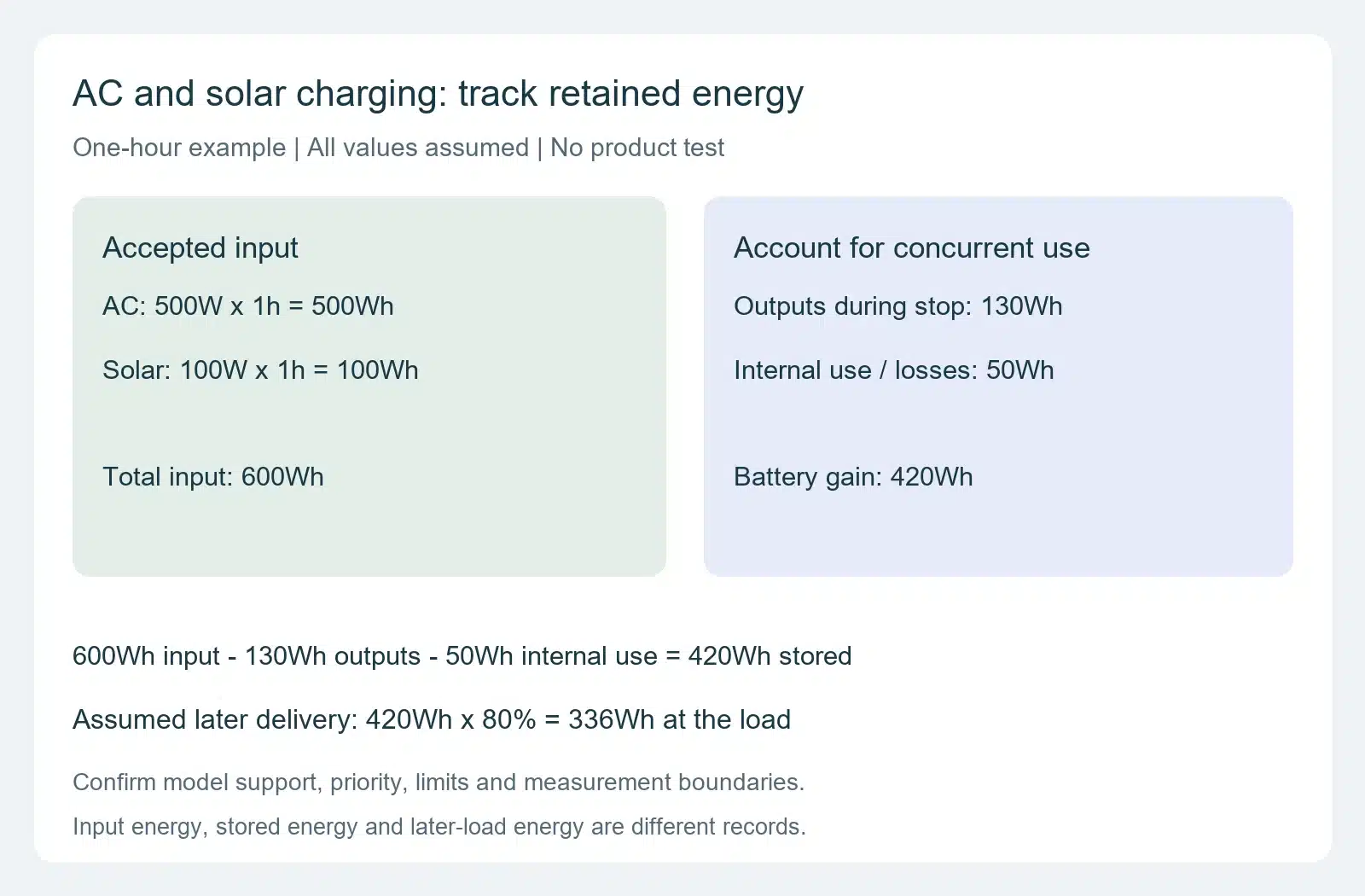
Energy added to storage also differs from energy delivered later to a device. If you assume 80% of that 420Wh can later reach the chosen load through its output path, the later-load contribution is 336Wh. That factor is another assumption. Replace it with an appropriate documented or measured value before relying on the result.
For comparison, a later 60W load running for five hours needs 300Wh at the load. In this example, the charging stop would contribute 36Wh more than that requirement. A six-hour session would need 360Wh and exceed the assumed contribution by 24Wh. Any reserve you intend to keep must come out of the available budget too.
Record starting energy as well as the energy gained. If the station already contains a usable battery reserve, include it once in your later-load budget. Don’t treat a one-hour charging gain as the whole battery capacity, or assume that an unchanged displayed percentage means neither input did useful work; connected loads may have consumed the incoming energy.
4. Check AC and solar charging modes and conditions
Before judging AC and solar charging performance, record the active mode and charge target. Scheduled charging, a reduced input setting or an upper battery limit can change the observed result. The relevant behavior comes from the exact model’s instructions.
The Anker C1000 Gen 2 A1763 manual, for example, describes an app-set upper charging limit from 80% to 100%. It also documents a periodic battery-level correction that can temporarily charge to 100% after 720 hours of operation when limits are set. Those are specific controls and exceptions for that model; another station may behave differently.
If charging reaches a configured target and stops, record the target before assuming that the second source failed. The charging-limit diagnostic deals with an unexpected stop at 80% or 90%. Keep that fault investigation separate from proving simultaneous source support.
Temperature can also interrupt a supported AC and solar charging session. The A1763 manual instructs users to stop using the station when its temperature alert appears and wait until the alert disappears; its high-temperature instruction includes allowing the station to cool. Follow the corresponding instructions for your model instead of repeatedly reconnecting sources or forcing a faster mode.
Use a location permitted by the manual, keep required ventilation clear, and protect the station and mains connections from weather. Panels may have an outdoor rating that the station lacks. A bag or sealed enclosure can protect against one exposure while obstructing airflow, so check the complete arrangement. For cold trips, the cold-weather power station checks separate storage, discharge and charging limits.
The available mains supply matters too. Use the documented charging cable and a suitable supply within the manufacturer’s requirements. At a campground or shared outlet, confirm the permitted load with the operator. A supported dual-input mode doesn’t authorize overloading a circuit, defeating a protective device or altering fixed wiring.
5. Record a supported AC and solar charging trial
Once support and compatibility are established, follow the manufacturer’s connection sequence and operating instructions for a trial. Use a representative charging window with enough room below the intended charge target. There is no reason to deeply discharge the battery solely to create that room.
Start with the documented arrangement and modest supported loads, if concurrent use is part of the plan. Observe the input readings, battery trend and any warnings. A single successful session establishes what happened under those conditions; it doesn’t prove every source combination, temperature or firmware version will behave the same way.
Keep an AC and solar charging record:
| Record item | Why it helps |
|---|---|
| Exact model, generation, region and firmware | Identifies the hardware and instructions that apply |
| Manufacturer support passage and required mode | Establishes permission for both inputs |
| Each source and its documented compatibility | Separates an input mismatch from combined control behavior |
| Starting/ending time and battery level | Defines the charging window and observed battery trend |
| Charge target, schedule and input settings | Explains intentional limits or stops |
| Source readings with their measurement boundary | Helps compare AC and solar contributions correctly |
| Concurrent loads and cumulative output energy | Accounts for incoming energy used during the stop |
| Temperature conditions, warnings and changes | Gives support a useful description of interruptions |
If the readings don’t match expectations, stop at the manufacturer’s warning or fault instruction. Review the support statement, settings and conditions before attempting another arrangement. Send the record to the manufacturer’s support team if the combined behavior remains unclear. Don’t open the station or improvise a connection to make the screen show more watts.
Use the observed session to revise the next-load budget. If it falls short, a longer supported charging opportunity, less concurrent use or a smaller later energy requirement may resolve the plan. Increasing panel size helps only when the documented solar and combined input limits permit it.
Questions to ask before buying
Ask the seller or manufacturer for the exact model’s simultaneous AC and solar charging support, the combined limit in the mode you will use, and the source priority. Also ask whether your intended outputs can operate during that arrangement and where the displayed input power is measured.
If the answer only repeats separate AC and solar maximums, the combined behavior is still unresolved. Compare models using the supported energy available during your actual stop and the later load you need to supply. The portable power station guides bring that charging opportunity into the wider output, energy and carrying decision.
Source note: This article uses manufacturer documentation and clearly labeled calculations. The earlier solar-fault draft’s unsupported hands-on and professional claims are withdrawn. No original product test is claimed here.